Description of faults
Lecture Index: Notebook
terms./ Description of idealized fault
components. / Fault zone rocks and
structures. / Fault recognition at
map scale. / A traditional fault classification.
/
Readings:
- Reading in Fossen, Structural Geology textbook, pages 119-126, and 135-138, 151-185
- suggested: Scholz, C. H., 1987, Wear and gouge formation
in brittle faulting; Geology, v. 15, p. 493-495. This is an introduction
to the scaling of various fault parameters.

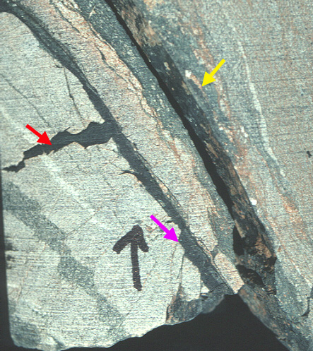
This
figure is from a core drilled into basement rocks of South Carolina
and shows a pseudotachylite injection vein (red arrow), a pseudotachylite
slip surface with secondary associated, high angle oblique microfaults
(violet arrow), and a chloritized fault breccia (yellow arrow).
The slip here is parallel to the gneissic layering seen in the
adjacent rocks. The rocks here are more mafic in composition, which is thought by some to promote pseudotachylite formation.
Notebook terms for week 2
- strike
and dip
- hanging wall and footwall
- cutoff lines
- net slip, dip slip, strike-slip
- piercing points
- dextral vs. sinistral
- fault breccia, gouge, flinty crush rock, pseudotachylites
- fault core versus damage zones
- breccias as polygenetic
- mylonites
- fault scarps
- striae, slickensides
- dilatancy
- drag folds
- types of fault terminations
- fault recognition criteria in the field
- Andersonian classification
- fault reactivation.
Description of idealized fault components
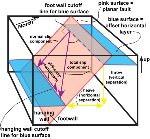 Faults or a smaller portion of a fault can sometimes be idealized
as a planar surface with a vector of slip in it and offset and
truncated layers, as depicted in the simplified diagram to the right. The diagram to the right visits the basic geometry and terms you should become familiar with. This diagram depicts a simplified case of horizontal layers that are offset. Dipping layers will usually have plunging cutoff lines associated with them. Note that there is an infinite number of lines that potentially connect the two cutoff lines. This means that cutoff lines by themselves are not adequate to allow the direction and amount of motion on the fault to be determined.
Faults or a smaller portion of a fault can sometimes be idealized
as a planar surface with a vector of slip in it and offset and
truncated layers, as depicted in the simplified diagram to the right. The diagram to the right visits the basic geometry and terms you should become familiar with. This diagram depicts a simplified case of horizontal layers that are offset. Dipping layers will usually have plunging cutoff lines associated with them. Note that there is an infinite number of lines that potentially connect the two cutoff lines. This means that cutoff lines by themselves are not adequate to allow the direction and amount of motion on the fault to be determined.
In this case, the following components are used to describe
the fault geometry:
- strike and dip of fault plane.
- orientation of slip vector.
- magnitude of slip vector.
- sense of motion.
- cutoff lines and piercing points:
- cut-off lines are where a layer gets truncated by a fault, and for a given offset layer there are two such cut-off lines on either side of the fault.
- piercing ponts are where a disctinve linear feature gets truncated by a fault. For example, if a fault crosses a channel sandstone in a formation, then there are two piercing points.
- connecting peircing points provides the total net slip vector. Realize, however that the actual path of movement through time could be zig-zag and more complicatedm and that there is an infinite number of possible paths between the hanging wall and footwall piercing points.
Total (net) slip vector = strike slip vector plus dip-slip component vector. Since the triangle formed by these three vectors is by definition a right triangle, this
is just one place that trig functions come in useful (as you will see in lab).

Here is an unlabeled diagram that you can use to practice and develop your understanding of basic fault geometry. If you click on here you should have a page size version that you can print. The purple arrow shows the net/total slip. Given this diagram and information try to label the diagram with the components labeled in the similar version above (cutoff lines, normal and strike-slip components, etc.). If you click here than you can find an answer. Realize that it will not help you nearly as much to just click to the answer - better learning comes from trying to work through it first.
Fault separations versus slip directions:

- heave and throw as horizontal and vertical separation components in cross section view (see diagram above).
- imp. distinction between separations and slip components. You
can have a horizontal separation and no strike-slip movement
or a throw and no dip-slip movement.
- Block diagram to the right shows an example of how a dipping layer that is displaced by pure dip-slip movement will have a strike-slip separation. In a map view it is easy, but incorrect, to think that this would be a strike-slip fault.
In reality and at larger scales faults are typically non-planar! This has
some very important implications as you will see.
- fault bend geometries. Often found in layered materials
(laminate behavior).
- listric: curved fault surfaces.
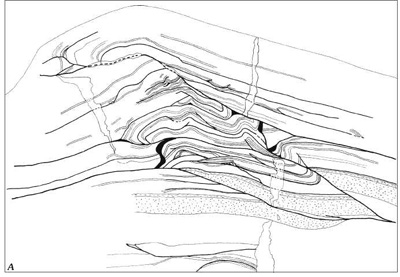 Hand specimen sketch example of non-planar faults. Note how the faults (darker lines) both follow then cut through the layers. Some of the non-planar fault character is not the original fault geometry but where earlier-formed faults were folded by movement along underlying non-planar faults. Image source: Pohn, H., Lateral Ramps in the Folded Appalachians and in Overthrust Belts Worldwide --A Fundamental Element of Thrust-Belt Architecture - USGS Bulletin 2163 - https://pubs.usgs.gov/bul/b2163/html/ .
- non-planar geometries require fault block internal deformation
in addition to simple riging body translation. Typically this occurs in the hanging wall for dipping faults, but also occurs with strie-slip faults. Later we will see how faults are often linked to more distributed deformation, and how how you define the boundaries of the fault zone can make a difference.

Turtleback detachment fault in Death Valley (dashed line) with rift fill fanglomerates and sandstones in hanging wall and mylonitized, brecciated and chloritized (retrograde metamorphism) basement rocks in the footwall. Note the small normal faults that displace the sandstone in the hanging wall and bend (sole) into the flatlying detachment.The sandstone layers inbetween these small normal faults have rotated clockwise (in this view) as this faulting occurred.
fault terminations:
- offset dispersal splays (relay or tri-shear termination). A fault
can be thought of as more than a surface, but more of a volume,
one whose constraining surfaces do not need to be parallel.
- transferrence (change of character).
- transferrence through distributed deformation.
- hinged faults: implications for slip directions and amounts.
- intersection with surface.
- elliptical offset gradient patterns on indiviudal fault. Slip gradients can be as low as 10 to 1 (for every unit distance along the fault, the slip decreases by .1 unit, so that a dip slip fault with 1 meter maximum movement on it may only be 20 meters long in map view). An interesting question is - what determines the slip gradient on a fault?

Block diagram showing an interior fault surface with slip vectors shown in brown. The maximum slip is in the interior and the slip decreases towards the tip-line fault margin. The slip gradient depicted here, as expressed in unit decrease per unit length, is higher here than is typical for rocks.

This is a map of the slip amounts on the subduction fault during the devastating earthquake that caused the tsunamis that created so much havoc. This is the picture for one slip event. The net slip on a fault from many events can also show a similar distribution of a maximum toward the center of an ellipse that grades out to a fault tip with zero displacement. Image source from: http://earthquake.usgs.gov/earthquakes/world/japan/031111_M9.0prelim_geodetic_slip.php.
Fault zone rocks and structures
 Some faults are pretty much a single and simple slip surface, but
most faults are manifest as a zone with distinctive rocks and
features related to the fault movement within them. Below are
some examples. Fault images
to feed your eyes.
Some faults are pretty much a single and simple slip surface, but
most faults are manifest as a zone with distinctive rocks and
features related to the fault movement within them. Below are
some examples. Fault images
to feed your eyes.
- breccias:
these are polygenetic!
- sedimentary breccias (e.g. talus accumulations).
- solution/collapse breccias.
- volcanic or intrusive breccias.
- impact breccias.
- fault breccias.
- how do you distinguish between various genetic types?
- associated dilatancy (dilatancy = volume increase).
- Right: Image of a gysum solution paleokarst breccia in Carboniferous carbonates of the Billefjorden, Spitsbergen area. The bedded material indicates there were multiple episodes of deposition of the breccias.
- images of a variety of breccias.
- fault cores:
- concentrated brittle deformation, original textures often destroyed.
- accomodates the bulk of displacement.
- distinctive hydrologic properties.
- damage zones (fault envelope):
- usually intense fracturing, but not alot of slip, with original textures preserved.
- deformation bands in sands often a part of damage zones.
- precursor or syn-slip?
- distinctive hydrologic properties that can differ substantially from the fault core.
- gouges:
- fine grained, cohesionless fault rock
in fault core.
- extreme milling versus clay alteration.
- should produce strain weakening and concentration of fault slip.
- flinty crush rocks.
- pseudotachylite (frictional melts).
- variety of types of mylonite (discussed
later since ductile in many ways).
- striae.
- slickensides fibrous mineral growths, often with steps that indicate the sense of motion.

- Above: Example of stepped slickenslides on bedding surface of Baraboo quartzite related to slip along that bedding surface. In this view movement is the block toward the viewer to the left and the block below to the right. Note the finger in lower left for scale.
- veining (ones with fibrous mineral veining especially informative).
- drag folds (will discuss more when we consider tri-shear zones).

View of a small normal fault in the Brule Formation strata of Slim Buttes, South Dakota, with the fault core and damage zones labeled. The tan line outlines an offset marker horizon.The damage zone in this case consists of joints parallel to the fault plane, some of which have small displacements. Joint clusters are common in this rock, and one interpretation is that this was originally a joint cluster that was reactivated as a slip plane as strain increased, a common type of history. Note how the fault core forms a fin and is erosionally resistent. This is in part because of differential cementation in the fault core, suggesting it may have served as a conduit for fluid flow at some point in time.
Fault recognition at map scale
How do you recognize faults in the field?
- fault zone and rocks often not exposed, so the map pattern and geologic traits of the rocks on either side of the fault may be all one has to work with.
- structural discontinuities and truncations do not necessarily
equate to a fault:
- intrusive contact.
- unconformity.
- layer parallel faults:
- difficult to recognize, but expected from a mechanical perspective.
- truncations may be low angle and less evident.
- disparity in deformation on either side.
- common with thrusts, where older on top of younger may give them away.
- presence of fault rock types, and associated
structures may give them away.
Map to right is part of the USGS Tapestry of Time geologic map and shows the truncation of the Appalachian structural features by the younger Cretaceous Coastal Plain sedimentary units (red arrows). Many traits clearly indicate that this contact is an angular unconformity - including the ages of the rocks involved, the interdigitate character of the contact, and the scale involved. However, subhorizontal faults can have a similar interdigitate map expression. Image source: https://pubs.usgs.gov/imap/i2720/ .
A traditional fault classification
 Andersonian classification: This classification is based both on observation of
what types of faults are common, and on theory guided by the idea
that the earth's surface tends to shape fault orientations. Real faults are more complicated, as we will see later in the course, but this is a useful starting classification.
Andersonian classification: This classification is based both on observation of
what types of faults are common, and on theory guided by the idea
that the earth's surface tends to shape fault orientations. Real faults are more complicated, as we will see later in the course, but this is a useful starting classification.
- normal faults.
- thrust faults.
- reverse faults.
- wrench faults.
The image to the right shows simplified schematic diagrams of the offset of layers with the arrow representing the direction of slip along the fault plan, which in three of the four examples are dip slip.
| fault type |
fault dip |
dip or strike slip |
hanging wall motion |
horizontal kinematics |
| normal |
60 degrees |
dip slip |
down |
extension |
| thrust |
30 degrees |
dip slip |
up |
contraction |
| reverse |
60 degrees |
dip slip |
up |
contraction |
| wrench |
subvertical |
strike slip |
NA |
both |
- reverse faults and reactivation.
- kinematic classification:
- contractional.
- extensional.
- strike-slip.
- transpressional.
Fault images
to feed your eyes.
Copyright Harmon D. Maher Jr., This may be
used for non-profit educational purposes as long as proper attribution
is given. Otherwise, please contact me. Thank you.